“Cable TV (CATV) House Wiring - How to Make a Distribution Panel”
By Ron Stultz
26 September 2005
Updated: 1 Feb 2019
Summary: where a home has a significant number of cable TV "drops", a cable TV (CATV) distribution panel may be the best way to organize all cables and ensure a quality, interference free signal at all connected televisions and Internet cable modems. Here, I provide information on constructing such a panel
Background:
In 1991, my current home was renovated and I made sure that most rooms had a cable TV, community access television (CATV), cable drop or access point, installed (12 total). At that time, each single cable consisted of 2 actual, separate, wires because this was required by the local cable company to receive all their "broadcast" channels.
From where the cable from the cable company entered the 1st floor of my 3 floor home, all cables run to various rooms terminated in one big tangle of cables with no connectors on any of them! And of course, none of the cables where labeled as to which room it went to.
What do to?
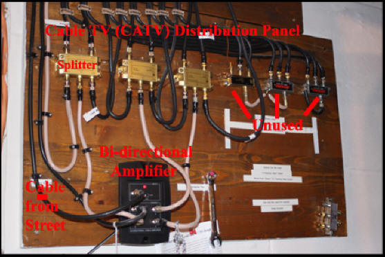
Cable TV Distribution Panel

What I decided to do was to build a cable TV (CATV) distribution panel. Above may look complex but it really isn't.
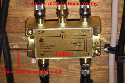
Splitters. As the single cable in from the cable company had to be connected to all room cable drop cables, I needed 3 (1 in and 4 out) splitters to handle the 12 room drops. I bought the best splitters I could find for this, meaning the widest bandwidth (5 - 2300MHZ). With so little dollar difference between the low-end splitter and the top-of-the-line, made no sense to go cheap.
Updated 1 February 2019:
Been told and I tend to believe that splitters do have a finite life and should be replaced every ? years? 10? Although a passive device, meaning it does not run on additional power of any type, some elements in it age quickly and can impact performance. If you have a problem on one set of cable drops, could well be a bad or aged splitter.
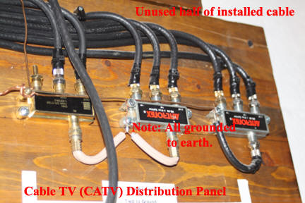
Eliminate interference. I was aware that when the electricians wired my home for electricity and cable, they paid no attention to the rule that says you never run a CATV cable parallel to an electrical power line, thus I knew if I did not take special measures, 60 cycle lines or interference would appear on the screen of all connected televisions. To eliminate interference, I (1) used heavy gauge wire and connected the case of all splitters to each other and then ran my ground wire to a nearby cold water pipe that I know was a solid earth ground (2) connected all those unused wires of my 2 wire cable to each other and to earth ground (3) placed a 50 ohm terminator on any and all splitter outputs or inputs that were not going to be used and (4) placed a terminator on all room drops that were not going to be hosting a TV right away.
.jpg)
.jpg)
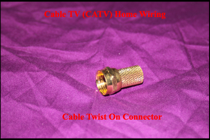
CATV Cable Connectors. As I said above, none of the cables terminating in my utility room had connectors on them, so I procured the best gold plated screw-on type connectors I could find. Again, the price difference between the cheapest and the best is so little money that the best makes sense here or did to me.
UPDATE: 2 FEB 2019.
Screw-on coax connectors just do not electrically or mechanically last (they get loose on cable over time) and don't use them if you can avoid it.
I have now gone to compressor coax connectors which are 100% better than the screw-on type.
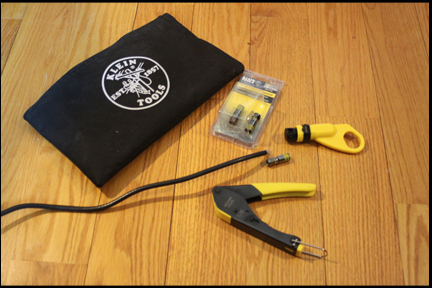
Above shows the compression connector kit that allows you to make perfect, last-forever, coax connections. There are several brands available, I just happen on this brand and like it.
Cable Amplifier. Each splitter reduces the signal strength it receives in by 7db. What "db" means is not important, only that the signal is diminished each time it passes through a splitter. So to counteract the 7db drop of my splitters, I added a 7db CATV amplifier. Because I use my cable for Internet, the amplifier I procured was bi-directional to allow signals to flow in both directions on the cable.
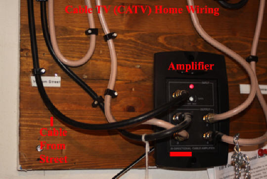
Wiring. From the street, the CATV enters the input of my bi-directional, powered, amplifier and then the amplifier supplies 4 amplified outputs. I use three of these outputs to go directly into splitters and the fourth is routed back out of the house, along the outside of my home to where it connects to a splitter. From the outside splitter a cable comes into my office for attachment to a cable modem and also into another room on the first floor that did not have a cable drop.
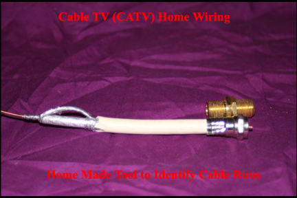
Cable Drop Labeling. Before each cable drop cable was attached to the splitter, I used a custom made tool to continuity test identify which room each drop went to. What I did was attach my test tool to the cable drop wall plate in a room and then using a continuity checker, tested each cable at my panel to find the shorted cable. I then labeled each cable drop cable.
And how does it work? Before I took the effort to construct my cable TV distribution system, I routed the cable company signal to a single splitter, which then went out on 2 cables to the locations where I had televisions. With this configuration, the signal on some channels was absolutely terrible and I had 60 cycle electrical interference lines scrolling across the screen on some channels. After my distribution panel, all interference is gone and all channels are bright, clear and solid.